What is a Binary Clock:
A Binary Clock is a clock that shows the time as a binary value. For example 12:49 will be displayed as 1100 110001 (it should be noted this is seperating hours and minutes as seperate binary values for the purpose of displaying).
Why this project:
The Binary Clock is a common engineering project. The reason I choose to tackle this project was due to dynamic nature of the project. A Binary Clock can be made as simple as by hard coding the values or adding additional layers such as using a RTC (Real Time Clock).
Process of this project:
For my particular project I wanted to incorporate an ESP8266 module for the primary function of decreasing the footprint used by components, with some added challenges for me to work around. The main challenge with the ESP8266 modules I used are two fold, first the plague of many electrical engineering projects: Limited GPIO pins. The second being that I had never previously worked with an ESP8266 module. I used existing code from examples to get the time, the using a serial command to display the values the ESP8266 was receiving. At this point I realized it was running based on UTC time and I adjusted accordingly for my time zone. This first step resolved some of my issues with familiarity with the module but still left me with the challenge of getting enough GPIO pins to display a 24 hour clock sans seconds. This was tackled by using 74HC595N bit shift registers, allowing me to effectivly turn 3 GPIO pins into 8 outputs per chip. My design uses a total of 13 LED’s so two registers were used to get the desired amount of outputs. One register controlled hours the other controlled minutes, this was done for ease of coding. Eventhough I could have used more inputs on the shift register to reduce useage on the other it made no sense since overal foot print would not change. Using the shift registers allowed me to easily incorporate arrays into my code and making it look slightly more professional. Aside from LEDS the last remaining components I used was 220 Ohm resistors to drop the current and prevent the LED’s from living a short but bright life. I added these resistors on the ground side of the LED’s, due them acting only to limit current the positioning is not crucial and it helped with the soldering of the LED side of the board.
Thoughts I had during this project:
-
Why bother with Shift registers? I can just use two EDP8266 modules I have plenty of them. The main reason I thought about this is because I have limited exposures to using Shift Registers and figured loading two ESP8266 modules with software (one would control hours and the other would control minutes) would be an easy copout. Since they both would get time using WIFI I wasn’t concerned about drift. I ended up deciding against this due to the increase in the footprint as well as it being an easy out rather than trying to find and work towards a more effective solution.
-
Why not use an RTC and an Atmega328P? Orginally I had just wanted to build an easy Binary Clock but realized I would appreciate someting new and more challenging in certain areas. (Also I only have 2 Atmega328’s lying around, I need to order more)
ESP8266 Versus RTC:
The pro’s and cons of each will be described in this section and the final reasoning why I picked the ESP8266 module (aside from the reasoning given above)
| ESP8266 Pro’s | RTC Pro’s |
|---|---|
| Smaller footprint (standalone) | Common, used in many projects |
| Highly accurate | Capability to retain time if powered off and moved |
| I have a lot of them lying around for some reason |
| ESP8266 Cons | RTC Cons |
|---|---|
| Limited GPIO pins | Larger footprint |
| Added complexity | Needs to be used with a microcontroller |
| Unfamiliar with it | Accuracy might be questionable (not a huge concern) |
| Requires internet connection to work |
Lessons learned:
There are a few things I learned doing this project that are worth noting down for future projects
Space management and component layout:
- While assembling the components I did not thing too much about how they should be oriented, this would come back to bite me when I got ready to solder the wires in place and realized I could have done a better job.
- I ended up using two Protoboards when I should have used one larger one to build everything on.
- Using protoboards was a bit messy and if I were to redo this project this way I’d buy some protoboards that have the side by side pads linked rather than all seperated.
Coding:
- No need to get very complicated, a few times I went off in to a rabbithole only to take a step back and realize the solution was a lot easier to implement then I was trying to.
- Array’s are your friend and not that scary, use of arrays saved me a lot of time and actually made the process a lot smoother.
Take your time:
- I wrote out all of the binary actions by hand first and was able to easily make changes to my code and wiring diagram before implementing everything. This saved me when I was wondering why I had an extra resistor that wasn’t being used.
- I cute a few wires way to short and struggled to get them to work. (Solution for this is in the works)
(End of lessons learned)
Things left to do:
The code works, the circuit works so what is left to tackle? For starters I will be adding a 3rd Protoboard and jumping the Register outputs and the LED Inputs to this board. This will give me some flexitiblity in how I want to orientate the whole design. I will also be getting some use out of my 3D printer and making a case to house this setup. I plan on adding a button to select different timezones using the free GPIO’s that I have left over. I did briefly consider adding a power supply to the setup but due to the nature of the Clock only working while on WIFI I don’t see much reason to work towards this goal.
Final thoughts and takeaway:
Although I loved the challenge I provided myself with this project and the future Rev2.0 additions I will be implementing I also realize I could have gone a lot simpeler with this setup. First off is return to form with an RTC, I would have saved myself a good amount of time with coding and had a lot more community support to lean on. Thats not to say that the ESP8266 does not have support. It was just a bit more of a learning curve. I also think that this project could be moved to an even smaller foot print using an RTC, Atmega328P and an HT16K33 with a 8x8 LED matrix attached to it. The LED’s take up a lof of real estate and having them all be on an 8x8 matrix would save a lot of space. (Plus no need for resistors) I might revisit this option just for fun and update this page if I build it, it likely won’t get a full write up as it is just being done as proof of concept (this is silly I know it can be done but ya know self satisifaction is important)
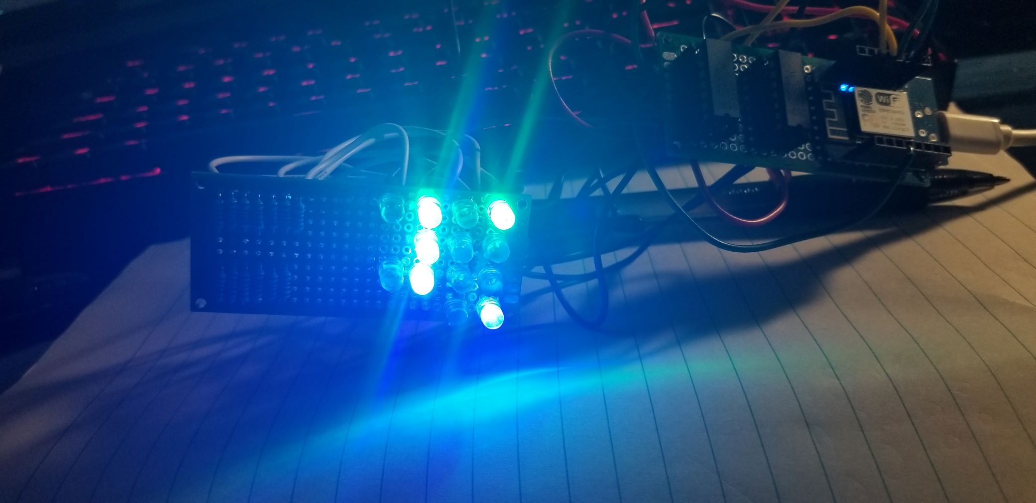
Images of the project along with the code will be uploaded here The code will also be available on my webpage in the “Binary_Clock_Code_RevX_X” File.
-The-Lifting-Engineer